


з·ҡи·ҜиӘӘжҳҺ
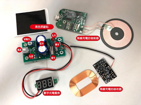
з„Ўз·ҡе……йӣ»зҡ„жҺҘ收еҷЁйҖЈжҺҘз·ҡи·Ҝең–е·Ұж–№зҡ„ијёе…Ҙз«ҜпјҢзӣҙжҺҘйҖЈжҺҘи¶…зҙҡйӣ»е®№ C1 йҖІиЎҢе……йӣ»гҖӮйӣ»е®№дёҠзҡ„йӣ»еЈ“з”ұж•ёеӯ—ејҸйӣ»еЈ“иЎЁйҮҸеәҰгҖӮS1 зӮәеҫ®еӢ•й–Ӣй—ңпјҢжҢүдёӢеҫҢпјҢ и¶…зҙҡйӣ»е®№дҫҝжңғйҖҸйҒҺйӣ»йҳ» R1 ж”ҫйӣ»гҖӮж”ҫйӣ»зӢҖж…ӢйҖҸйҒҺзҙ…иүІзҡ„зҷје…үдәҢжҘөз®Ў L1 зӣЈеҜҹпјҢж”ҫйӣ»еҲқжңҹ L1 жңғзҷје…үпјҢ當 L1 зҶ„ж»…еҫҢпјҢйӣ»е®№дёҠд»Қж®ҳз•ҷжңүзҙ„1.5 Vзҡ„йӣ»еЈ“пјҢз№јзәҢжҢүдёӢдёҖеҲҶйҗҳеҸҜд»ҘдҪҝйӣ»е®№ж”ҫйӣ»иҮізҙ„0.3 VгҖӮй–Ӣй—ң S2 зҡ„еҠҹз”ЁжҳҜйҒёж“Үйӣ»и·Ҝзҡ„йҒӢдҪңжЁЎејҸпјҢиӢҘ S2 иҷ•ж–јеҪҲиө·зҡ„зӢҖж…ӢпјҲеҰӮз·ҡи·Ҝең–жүҖзӨәпјүпјҢйӣ»е®№дҫҝжңғзӣҙжҺҘйҖЈжҺҘ J1 дёҠзҡ„йҰ¬йҒ”пјҢиӢҘйӣ»е®№дёҠжңүи¶іеӨ зҡ„йӣ»еЈ“пјҢйҰ¬йҒ”дҫҝжңғиҪүеӢ•пјҢз¶ иүІзҷје…үдәҢжҘөз®Ў L2 дәҰжңғдә®иө·гҖӮ
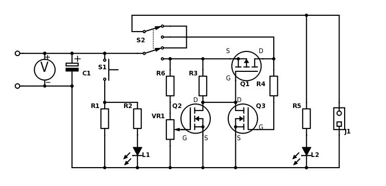
жӯЈеёёжҜ”иіҪжҷӮпјҢй–Ӣй—ң S2 жҮүиҷ•ж–јжҢүдёӢзӢҖж…ӢгҖӮйҖҷжҷӮеҖҷйӣ»е®№йҖЈжҺҘдәҶиҮӘеӢ•и§ёзҷјз·ҡи·ҜпјҢ當йӣ»е®№е……йӣ»иҮіз”ұеҸғиіҪиҖ…йҒёе®ҡзҡ„йӣ»еЈ“еҫҢпјҢйӣ»и·ҜдҫҝжңғиҮӘеӢ•еҗ‘йҰ¬йҒ”дҫӣйӣ»пјҢзӣҙиҮійӣ»е®№дёҠзҡ„йӣ»еЈ“дёӢйҷҚиҮізҙ„ 0.3 VжҲ–д»ҘдёӢгҖӮQ1 жҳҜ P йҖҡйҒ“зҡ„е ҙж•ҲжҮүжҷ¶й«”з®ЎпјҢе…¶йҒӢдҪңж–№ејҸеҫҲз°Ўе–®пјҢ當й–ҳжҘө G зҡ„йӣ»еЈ“зӮәй«ҳжҷӮпјҢS иҲҮ D д№Ӣй–“зҡ„йҖҡйҒ“зӮәй—ңй–үзӢҖж…ӢпјҢзӣёеҸҚпјҢ當 G зҡ„йӣ»еЈ“зӮәдҪҺжҷӮпјҢйҖҡйҒ“дҫҝжңғжү“й–ӢпјҢS еҸҠD д№Ӣй–“дҫҝиғҪйҖҡйӣ»пјӣеӣ жӯӨпјҢе ҙж•ҲжҮүжҷ¶й«”з®ЎеҸҜд»ҘиҰ–зӮәдёҖеҖӢз”ұйӣ»еЈ“жҺ§еҲ¶зҡ„й–Ӣй—ңгҖӮQ2 еҸҠ Q3 зҡҶзӮә N йҖҡйҒ“зҡ„е ҙж•ҲжҮүжҷ¶й«”з®ЎпјҢиҲҮ P йҖҡйҒ“ Q1 зҡ„еҲҶеҲҘеңЁж–јжҺ§еҲ¶е…¶й–ӢиҲҮй—ңзҡ„йӣ»еЈ“зӣёеҸҚпјҢеҚій–ҳжҘө G зҡ„йӣ»еЈ“й«ҳжҷӮ S иҲҮ D д№Ӣй–“зҡ„йҖҡйҒ“йҖҡйӣ»пјҢйӣ»еЈ“дҪҺжҷӮдёҚйҖҡйӣ»гҖӮ
йӣ»е®№дёҖй–Ӣе§Ӣе……йӣ»пјҢ Q1 зҡ„й–ҳжҘө G йҖҸйҒҺйӣ»йҳ» R3 жҺҘиҮіијғй«ҳйӣ»еЈ“зҡ„йӣ»е®№дёҠпјҢеӣ жӯӨ Q1 дёҚйҖҡйӣ»пјҢйҰ¬йҒ”дёҚжңғиҪүеӢ• гҖӮQ2 зҡ„й–ҳжҘө G йҖЈжҺҘиҮіеҸҜи®Ҡйӣ»йҳ» VR1 дёҠпјҢVR1 жҺҘй§ҒжҲҗзӮәеҲҶеЈ“йӣ»и·ҜпјҢеӣ жӯӨпјҢйҡЁи‘—йӣ»е®№дёҠзҡ„йӣ»еЈ“еӣ е……йӣ»иҖҢдёҠеҚҮпјҢQ2 зҡ„й–ҳжҘөйӣ»еЈ“дәҰжҢүжҜ”дҫӢдёҠеҚҮпјҢзӣҙиҮій–ҳжҘөйӣ»еЈ“дёҠеҚҮиҮізҙ„ 0.7 V жҷӮпјҢQ2 дҫҝжңғйҖҡйӣ»гҖӮиӘҝзҜҖ VR1 еҸҜж”№и®ҠеҲҶеЈ“зҡ„жҜ”дҫӢпјҢеҫһиҖҢжҺ§еҲ¶йӣ»е®№е……йӣ»иҮійӮЈдёҖйӣ»еЈ“ж°ҙе№іжүҚи§ёзҷј Q2 зҡ„е°ҺйҖҡгҖӮеҜҰйҡӣдҪҝз”ЁжҷӮпјҢй ҶжҷӮйҮқж–№еҗ‘иҪүеӢ• VR1пјҢйӣ»е®№дҫҝйңҖиҰҒе……йӣ»иҮіжӣҙй«ҳйӣ»еЈ“жүҚжңғи§ёзҷјз·ҡи·ҜйҖҡйӣ»пјҢеҸҚд№ӢдәҰ然гҖӮ
當 Q2 йҖҡйӣ»еҫҢпјҢQ1 зҡ„й–ҳжҘө G йӣ»еЈ“дҫҝжңғдёӢйҷҚиҮіжҺҘиҝ‘ 0 VпјҢжүҖд»Ҙ Q1 дҫҝжңғе°ҺйҖҡпјҢдҫӣйӣ»зөҰйҰ¬йҒ”гҖӮQ3 зҡ„еҠҹз”ЁжҳҜзўәдҝқ Q1 дҝқжҢҒеңЁйҖҡйӣ»зҡ„зӢҖж…ӢпјӣиӢҘзңҒеҺ»дәҶ Q3пјҢ當йӣ»е®№еӣ ж”ҫйӣ»иҖҢйӣ»еЈ“дёӢйҷҚдәҶдёҖй»һпјҢQ2 дҫҝжңғеҒңжӯўйҖҡйӣ»пјҢеҫһиҖҢд»Ө Q1 дәҰеҒңжӯўйҖҡйӣ»пјӣйҖҷжЁЈпјҢйӣ»е®№жүҖе„Іеӯҳзҡ„йӣ»иғҪдҫҝдёҚиғҪе……еҲҶйҒӢз”ЁгҖӮз”ұж–ј Q3 зҡ„й–ҳжҘө G йҖҸйҒҺйӣ»йҳ» R4 йҖЈжҺҘеңЁйӣ»еЈ“зҡ„ијёеҮәз«ҜпјҢжүҖд»Ҙ當 Q1 йҖҡйӣ»зҡ„жҷӮеҖҷпјҢQ3 зҡ„й–ҳжҘө G йӣ»еЈ“дҫҝжңғи®Ҡй«ҳпјҢQ3 дҫҝжңғйҖҡйӣ»пјҢзөҗжһңдҪҝ Q1 зҡ„й–ҳжҘө G йӣ»еЈ“и®ҠдҪҺпјҢйҖҷжЁЈдҫҝеҸҜд»Ҙзўәдҝқ當 Q1 дёҖж—Ұй–Ӣе§ӢйҖҡйӣ»пјҢдҫҝжңғз№јзәҢдҝқжҢҒеңЁе°ҺйҖҡзӢҖж…ӢпјҢзӣҙиҮійӣ»е®№дёҠзҡ„йӣ»еЈ“дёӢйҷҚиҮійқһеёёдҪҺзҡ„ж°ҙе№ізӮәжӯўгҖӮ
иӢҘжҠҠ VR1 й ҶжҷӮйҮқж–№еҗ‘ж—ӢиҪүиҮізӣЎй ӯпјҢз·ҡи·Ҝдҫҝи®ҠжҲҗжүӢеӢ•йҒӢдҪңгҖӮеӣ зӮә當 VR1 й ҶжҷӮйҮқж–№еҗ‘иҪүиҮізӣЎй ӯпјҢдҫҝзӯүж–јжҠҠ Q2 зҡ„й–ҳжҘө G жҒҶеёёйҖЈиҮі 0 VпјҢзөҗжһңжҳҜз„Ўи«–йӣ»е®№зҡ„йӣ»еЈ“е……иҮіеӨҡй«ҳпјҢз·ҡи·ҜйғҪдёҚеҸҜиғҪиў«и§ёзҷјгҖӮйҖҷжҷӮеҖҷпјҢдҫҝеҸҜд»ҘдҪҝз”Ё SW2 дҪңжүӢеӢ•ж“ҚдҪңпјҡе……йӣ»жҷӮжҢүдёӢпјҢе……еӨ йӣ»жҷӮеҶҚжҢү SW2 дҪҝе…¶еҪҲиө·пјҢйҰ¬йҒ”дҫҝжңғеҚіжҷӮй–Ӣе§ӢиҪүеӢ•гҖӮ
жіЁж„ҸдәӢй …
- еҝ…й ҲиҰҒжҺҘдёҠйҰ¬йҒ”пјҢз·ҡи·ҜжүҚеҸҜд»ҘжӯЈеёёйҒӢдҪң
- жҺҘ收з·ҡеңҲйҷ„жңүдёҖзүҮй»‘иүІзҡ„еұҸи”ҪиІјпјҢеҝ…й Ҳж”ҫеңЁжҺҘ收з·ҡеңҲеҫҢжүҚеҸҜд»ҘжӯЈзўәе……йӣ»
- зҷје°„з·ҡеңҲиҲҮжҺҘ收з·ҡеңҲд№Ӣй–“иҰҒдҝқжҢҒжңҖе°‘2 mm зҡ„и·қйӣўпјҢеҗҰеүҮе……йӣ»жңғдёҚз©©е®ҡ
- еҸғиіҪиҖ…еҸҜд»ҘиҮӘз”ұйҒёз”ЁеҗҲйҒ©зҡ„з„Ўз·ҡе……йӣ»жҺҘ收зө„件пјҢе”ҜйңҖжіЁж„Ҹеҝ…й Ҳе…је®№еӨ§жңғдҫӣжҮүзҡ„зҷје°„зө„件
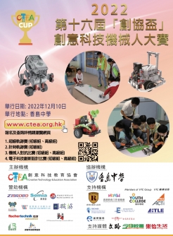
жҜ”иіҪи©іжғ…еҸҠиіҪиҰҸи«ӢзҖҸиҰҪ HKTREE еӨ§жңғз¶Із«ҷпјҡhttp://www.hk-tree.org/tc/index.html
Description of circuit
At the left side of the circuit diagram, the receiver of the wireless charging circuit is connected to the input terminals, which is connected directly to the super capacitor C1 for charging. The voltage stored on the capacitor is measured by an attached digital voltmeter. S1 is a micro-switch that when pressed down, will discharge the capacitor through resistor R1. The status of discharge can be monitor by the red LED (L1). In the beginning, the LED will light up. When the light has dimmed out, about 1.5 V will still be found on the capacitor. Continue to hold down the switch for one more minute can discharge the capacitor to about 0.3 V. The function of the switch S2 is to select the working mode of the circuit. If it is at the pop-up state (as shown in the circuit diagram), the capacitor is connected directly to the motor via J1. If there is enough charge on the capacitor, the motor will start turning and the green LED (L2) will light up.
During the competition, the switch S2 should keep pressed down. In this way, the capacitor is connected to an automatic triggering circuit. When the capacitor has charged to a predetermined voltage, the circuit will power the motor automatically until the voltage on the capacitor has fallen to about 0.3 V or below. Q1 is a P-channel field effect transistor. Its operation is simple. When the gate (G) voltage is high, the channel between S and D is shut down. On the contrary, if the voltage at gate (G) is low, the channel will be opened, and current can passes through S and D. As a result, a field effect transistor can be considered as a voltage-controlled switch. Q2 and Q3 are N-channel field effect transistors, the difference between N-channel and P-channel is that they operated in the opposite way. i.e., when the gate (G) voltage is high, current can pass through S and D. They are not conducting when the voltage at G is low.
When the capacitor has started charging, the gate (G) voltage of Q1 is being pulled high by resistor R3. As a result, Q1 is not conducting and the motor will not turn. The gate (G) of Q2 is connected to the voltage divider formed by the variable resistor VR1, therefore, when the voltage on the capacitor is raising, the gate (G) voltage of Q2 will also rise in proportion. If the gate (G) voltage of Q2 has raised to about 0.7 V, Q2 will conduct. Adjusting VR1 can change the proportion of the voltage divider so that the triggering voltage can be set to any desired level. In practice, turning VR1 clockwise will increase the voltage for which the capacitor has to charge up before the motor is being triggered to run and vice versa.
When Q2 conducts, the gate (G) voltage of Q1 will be pulled down to nearly 0 V, consequently, Q1 will conduct and supply current to the motor. The function of Q3 is to keep Q1 conducting. If Q3 is omitted, then Q2 will stop conducting when the voltage on the capacitor has felt a small amount due to discharge, causing Q1 to stop conducting. As a result, the charge stored in the capacitor will not be fully utilized. As the gate (G) of Q3 is connected to the output terminal via the resistor R4, when Q1 is conducting, the gate (G) voltage of Q3 will be high. Q3 will conduct, pulling the gate (G) voltage of Q1 low. Therefore, once Q1 has started conducting, Q3 will keep Q1 conducting, until the voltage on the capacitor has fallen to a very low level.
If VR1 is turned fully clockwise, the circuit can be used manually. Because when VR1 is turned fully clockwise, it connects the gate (G) of Q2 to 0 V constantly. As a result, no matter how high the capacitor has been charged up, the circuit will not be triggered. Therefore, the circuit can be used manually. Push down SW2 when charging the capacitor. Then push again to release SW2 to start the motor.
Important points:
- Motor must be connected for the circuit to work properly
- There is a shield (black in colour) that must be placed behind the receiving coil for correct charging
- The distance between transmitting and receiving coil should be keep at least 2 mm, otherwise, the charging may be unstable.
- Participants may use any wireless receiving unit. However, it must be compatible to the transmitting unit provided.
For further informations regarding the competition, please visit the official HKTREE websiteпјҡhttp://www.hk-tree.org/tc/index.html
иЁӮй–ұж–№жі•пјҡ и«ӢжҢүжӯӨиҷ•
иЈңиіјжҹҘи©ўпјҡжӯЎиҝҺиҮҙйӣ»гҖҠд»Ҡж—Ҙж Ўең’гҖӢиЁӮй–ұйғЁ 2342-8298 (鄧е°Ҹе§җ)